Tutorials
Using your WWU ESRI Account
Click on the tabs below for instructions on how to use your ESRI account and log into ArcGIS Pro and Online, both on and off campus. These instructions apply to academic staff and students.
Facility staff should contact Nancy Larson to set up an account.
If there are any issues with your account, email Natalie Furness.
Logging into ArcGIS Online and Pro follow the same instructions.
On the ArcGIS Sign In screen, click the option for "Your ArcGIS organization's URL." Enter wwu and press Continue.
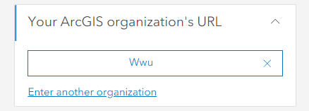
You may have to click the blue box that says Western Washington University.
You may need to log in with your WWU username and password, like you are logging into Canvas or a campus computer.
There are prerequisites for downloading ArcGIS Pro on a personal computer. To download and use ArcGIS Pro successfully, you need:
- A Windows computer.
- A computer that meets current system requirements.
- Download/storage space on your computer.
If you are a Mac user, there are some options you can explore to run the program. Check your system requirements, then select one of these options:
Once you have checked that your computer can run ArcGIS Pro successfully, you can install the program on your computer.
- Log into ArcGIS Online with your WWU username and password.
- Click your username in the upper right-hand corner and select My Settings in the drop-down menu.
- Click Licenses on the side bar.
- Scroll down and select the Download ArcGIS Pro button.
- Choose English (Version 3.x) and click Download.
- Open the .exe file that downloaded and follow the instructions to install the program.
Your WWU user account will remain active as long as you have a current WWU account. This means that once you graduate or leave WWU, your account will no longer be accessible. This means you will NOT be able to:
- Edit any of your published/online content.
- Use your ArcGIS Pro license / ArcGIS Pro.
- Use the ESRI Academy online tutorials and training materials.
If there is content that you would like to retain ownership of, your options are:
- Create a free, public ArcGIS Public Account.
- Purchase a license either for Pro or Online. An individual, non-commercial license is $100 a year.
- Have access to a new academic institution or employer that has an account with space to accept your work.
- Ask to transfer your content to a different student, staff, faculty, or the Spatial Institute at WWU. Contact Natalie to do this.
For instructions on transferring your content, see this article. Natalie can answer any questions and assist as needed.
Cartography
Foundations
Learn about what components all good maps should have.
To add Map Frame Grids and Graticulates to your map:
- Insert a map frame on a layout.
- From the insert ribbon, click the grid button.
- Choose one of the pre-defined graticules or grids
- Graticulates are in latitude and longitude.
- Grids are in specified units (feet, meters, etc.)
- The chosen grid will apply and be added to the contents as part of the map frame.
To modify grid/graticulate properties:
- Select the grid and choose the format ribbon.
- Select Map Grid, Labels, Tics, Gridlines, or Neatline from the drop-down menu to adjust basic properties.
- To modify advanced properties, right click on the grid in layout contents and choose properties.
- Choose Map Grid, Labels, Tics, Gridlines, or Neatlines to access sub-tabs and sections in each property.
Tips:
- To turn lines off and just have tic marks and labels at the edge of the map, select Gridlines > Properties > Layers and uncheck the visibility box.
- Specify a coordinate system with a grid by selecting Map Grid > Options > Coordinate System.
- Specify a certain interval for grid spacing by selecting Map Grid > Components > Interval.
- Labels can be adjusted by selecting Labels > Gallery or Properties.
- Label placement can be adjusted by selecting Map Grid > Components > Vertical and checking the N, S, E, or W to draw labels on specified side. Unchecking the box will remove the labels.
Need further help? See this tutorial about choosing the right grid.
To add a map frame on a layout that is not the default rectangular shape:
- Begin by selecting the map frame and choosing a rounded coordinate system projection.
- Navigate to your map properties and choose the coordinate system tab.
- Expand the Projected Coordinate System tab.
- Scroll down and expand the World or World (Sphere-Based) folder.
- Robinson and Natural Earth are common projections used, but explore this folder.
- World from Space coordinate system is in the World, but not sphere-based folder. This coordinate system can be modified to center on the latitude and longitude of your map area.
- Consider whether or not you want the border or background fill on or off for this map frame or adding a graticule/grid.
See this ESRI tutorial for tips on working with scale bars.
To learn about legends and modifying them, see this tutorial.
Symbology
To create hatching symbology:
- Select a polygon layer in the map contents.
- Right-click on the layer and choose Symbology.
- Select your symbology type.
- Click on the colored rectangle to Format Symbol.
- Once the pane appears:
- Choose the Properties tab.
- Choose the Layers sub-tab.
- In the fill type drop-down list, choose Hatched Fill.
- You can specify line symbol, color, width and pattern angles, separation, and offsets.
- Apply!
Interior buffer is similar to the inner glow options in Adobe Illustrator.
![]()
To get this effect:
- Select unique values for the polygon layer's symbology.
- For each fill, open the symbol Properties > Layer.
- Turn the outline layer off.
- Specify a gradient fill.
- Tweak the gradient properties for each polygon so the color, number of gradients, size, etc. create this outline effect.
There are a lot of styles available online for download to use in your projects. These are downloaded as a style file, which you then need to add manually to your project.
- Download the style you want (ESRI Style Gallery).
- In your project, open the catalog pane and click on the Project tab.
- Right click on the Styles folder and choose Add.
- Browse to where you stored your style file.
- Click OK to add the style.
If you are using multiple computers, you should put your style file in your project folder. When you move the entire folder for back-ups and storage, you will be able to locate and install the file on any computer you use. You may need to re-add the style on the other computers.
If you create some symbology you particularly like, you can create your own style file.
- Open the catalog pane and expand the styles folder.
- Right click on the styles folder and choose New > New Style.
- Find the location where you want to save the style and name it.
- Save.
This allows you to choose your own style set from the Save Symbol to Style dialog box.
Labels & Annotation
To convert labels to annotation:
- Right click on a layer in your content pane and turn on the labels for that layer.
- Specify the field you want to use for the labels and change your scale, font, color, size, etc. as desired.
- Right click on the layer in the contents pane and select Convert Labels to Annotation.
- Confirm that all of the autofill data is correct.
- Specify the conversion scale (what scale is your map layout going to be at?)
- Change the anno suffix, geodatabase if needed, and output layer named (default is named GroupAnno).
- Run!
To edit annotation:
- You can create new annotation by going to the Edit ribbon and hitting Create, similar to creating spatial features.
- You can also delete annotation by selecting an annotation and deleting it.
- You can edit what each annotation looks like, including moving it, curving it, adding a halo, changing font, and more.
Remember that once annotation has been converted, they become detached from features (labels remain dynamic and attached).
If there is not enough room to display labels, Pro will not place all of the labels.
To see all labels:
- Select the layer that is labeled, right click, and go to Labeling Properties.
- Hit the Position tab.
- Select the Conflict Resolution subtab.
- In the unplaced labels tab, check the box to never remove (place overlapping).
- In this tab, you can also specify whether or not you would like to allow duplicate labels.
To create curved labels:
- You can select one of the curved label options from the labels placement section of the labeling ribbon OR
- Right click on the layer in the map contents and navigate to labeling properties.
- In the pane, choose the position section and then position subsection.
- From the placement drop-down choose one of the placement options (like river or contour).
To create curved annotation (from non-curved labels):
- Select an annotation string.
- From the edit ribbon, click vertices.
- Right click on the baseline (between the two end vertices) and choose change segment / to bezier curve
OR
- Select an annotation string
- Choose vertices from the Tools group of the edit ribbon.
- Annotation line will show on the selected text, which will be green and red vertices.
- Choose the continue features tool on the context menu.
- From the line segment menu, click Arc Segment.
- From Arc Segment, select Bezier Curve Segment tool.
- Add a new vertex by clicking once at the approximate location where a new vertex should be located.
- To add a blue handle, click a second time at the approximate location of the handle.
- Do this at least one more time.
- Delete the original vertices from the Delete Vertex tool.
- This should leave only the new vertices with the blue handles.
- Hit finish.
- Now you can select the annotation string and move the vertices around (as well as the handles) to adjust the curve.
Halos for Labels:
- Navigate to Label Properties.
- In the Label Class pane, click the symbol tab and general subtab.
- Expand the halo section.
- Choose a halo symbol - commonly, this is white.
- Adjust your color, width, transparency, and size as desired.
- Apply!
Halos for Annotation:
- Select an annotation string and go tot he attributes button on the edit ribbon.
- Choose the annotation subtab.
- Click the symbol button.
- Go to the properties subtab and expand the halo section.
- Select the halo and specify as desired.
- Apply!
If you would like to remove a portion of the conflicting layer rather than using something like a halo:
- Do as much text formatting on your annotation as possible. Do all necessary positioning.
- Select one or more annotation strings you would like to make knockouts for.
- Open the Feature Outline Masks geoprocessing tool.
- Input layer: Annotation with the selected strings (or whole layer).
- Output name as desired.
- Coordinate system should match.
- Margin is the desired size of mask - good to start at 1 pt and go from there.
- Accept all other defaults and run.
- FeatureOutlineMask layer should be created and added. You can turn it on and look at it, but turn it back off after.
- In the Contents pane, select the conflicting layer (that you want things knocked out of).
- From the Appearance ribbon, open the masking drop down menu. Click the featureoutlinemask layer.
- This should knock out the portions of the feature layer where they overlap with this mask layer!
If you need to move a text string after this, you need to move both the featureoutlinemask layer polygon and the text string.
Add Leader Lines to Labels:
- Determine what scale you want your final map to be.
- Right click on the layer and choose labeling properties.
- In the Label Class pane, choose the Symbol section and then the general subsection.
- Expand the callout section and choose a callout from the callout drop-down menu.
- Adjust properties as desired.
- Apply.
Add Leader Lines to Annotation:
- If your annotation needs some leader lines and doesn't already have them on, you can select the annotation string you want.
- From the Edit ribbon, choose the annotation tool.
- Right click on the annotation and choose Add Leader.
- Adjust as desired.
To stack a label:
- Right click on the labeled layer in the map contents and choose labeling properties.
- Choose the position section and then the fitting strategy subsection.
- Check the box beside Stack Labels.
- Adjust the Stack properties as desired
- Forced stacked labels are always on multiple lines.
- Un-forced labels are unstacked if there is room on the single line.
To stack annotation:
- Open the attributes pane for an annotation text string.
- Manually enter line breaks (Enter) where needed.
Key Numbering is an automated way of labeling the features with 1, 2, 3 or A, B, C and then moving the labels to a nearby list.
There are two components to making a key list:
- Create a key numbering group
- Assign the group to a particular layer's labels.
Create the Key Numbering Group:
- Go to the Labeling Ribbon and select the More drop-down menu from the Map group.
- From this drop-down menu, check to be sure that the box for Use Maplex Label Engine is checked.
- Choose Key Numbering.
- In the dialog box, you can tweak the default group or make a new one.
- Check the box for Always Place Labels with Key Numbers.
- Adjust settings as desired (tips found here)
Assigning the Group to Labels:
- Configure labels as desired for the layer.
- Choose the class you want to apply key numbers for.
- Click the positions tab and then the fitting strategy subtab in the labels properties pane.
- Expand the Key Number section.
- From the Group Name drop-down, choose the Key Numbering Group you wish to use (like the Default one).
- It will refresh and you can see the effect.
You can choose to use multiple classes with different key numbering - different styles or only having some labels numbered this way.
There are multiple preset styles you can use to adjust text.
- Navigate to the Text Symbol section of the Labeling ribbon.
- You can choose boundary, landform, water labels, etc.
- Water labels create blue italic labels, while boundary, capital, and landform will make all cap labels.
- You can adjust beyond these presets by right clicking on the layer and going to Labeling Properties.
- In the Label Class plane, choose the symbol section and then the general subsection.
- For all caps or all lower case:
- Expand the appearance section.
- Change Text case to Normal, Lower, Upper, or Small Caps.
- For super or subscript:
- Expand the appearance section.
- For Position Adjustment, choose Normal, Superscript, or Subscript.
You can select what labels you use or modify. You can also choose what to label using expressions:
- Right click on the layer and go to labeling properties.
- Choose the label calss to modify.
- You can select the language you want, but this example will use Arcade.
- Upper case: upper($feature.name)
- Lower case: lower($feature.name)
- Proper case: proper($feature.name)
- Combine text and field: 'Text here ' + $feature.name
- Combine labels: $feature.name + ' ' + $feature.POP
- Line break: $feature.name + TextFormatting.NewLine + $feature.POP
- Number field label with separators: text($feature.POP,'#,###')
- Bold: "<BOL>" + $feature.CNTRY_NAME